
Hydroelectric Gearbox: How It Works, 3 Main Types, and When It’s Skipped
What Is a Hydroelectric Gearbox?
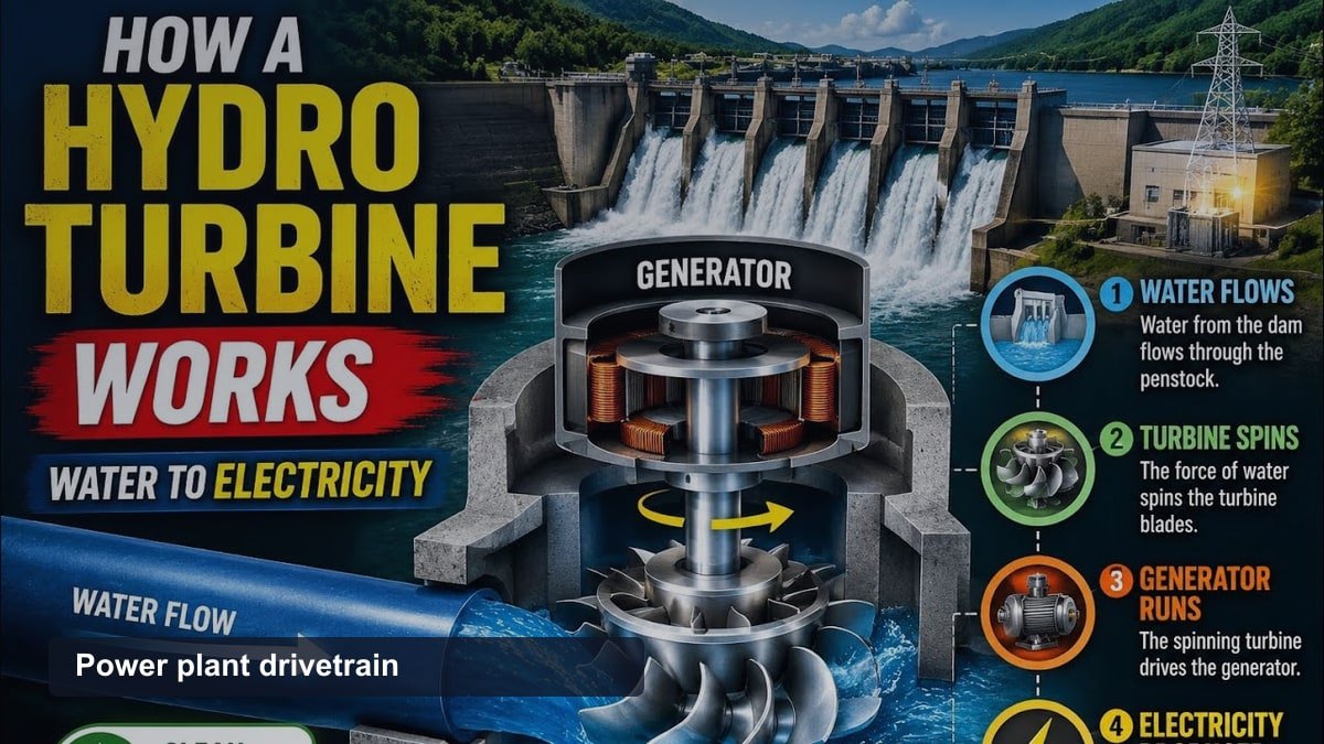
A hydroelectric gearbox is a mechanical device that connects a water turbine to an electrical generator and increases the turbine’s rotational speed to the level the generator needs. It is also called a speed increaser or a step-up gearbox.
Water turbines, especially in small or low-head plants, often spin too slowly to drive a generator efficiently on their own. The gearbox sits between the two components. It multiplies the turbine’s low RPM into the higher RPM a generator needs to produce electricity at the correct grid frequency.
The three most common gearbox types in hydropower are parallel-shaft, planetary, and bevel-helical designs. Each type suits a different combination of power output, shaft layout, and available space inside the powerhouse. Demand for this equipment ties into the broader speed-increaser gearbox market. That market, which spans hydroelectric, wind, and industrial applications, was valued at approximately $2.5 billion and is projected to grow at about 5.5 percent annually through 2030.
How Does a Hydroelectric Gearbox Work?
A hydroelectric gearbox works by meshing gears of different sizes to change rotational speed as power flows from the turbine shaft to the generator shaft. A small input gear connected to the turbine turns a larger set of internal gears, and the output shaft spins faster than the input shaft.
Turbine type and site conditions set the natural speed the gearbox has to work with. Kaplan turbines, used at low heads with high flow, typically spin between 54 and 450 RPM. Francis turbines, suited to medium heads, typically spin between 75 and 1,000 RPM. Generators paired with a gearbox typically run at standardized speeds such as 900, 1,200, or 1,800 RPM, depending on the number of poles and the local grid frequency.
Closing the gap between turbine speed and generator speed sets the gearbox ratio, which for most geared hydro installations falls somewhere between about 2:1 and 30:1. Micro-hydro systems with unusually slow turbines can need a much larger ratio, up to 100:1. Many of these smaller systems now skip the gearbox entirely in favor of a direct-drive generator instead.
What Are the Main Types of Hydroelectric Gearboxes?
Hydropower plants use 3 main gearbox configurations, distinguished mainly by shaft arrangement.
| Gearbox Type | Shaft Configuration | Typical Use | Key Trait |
|---|---|---|---|
| Parallel-shaft | Input and output shafts run parallel | Small to mid-size hydro plants | Simple design, widely available, moderate torque capacity |
| Planetary | Sun, planet, and ring gears share the load | Compact installations needing high torque in limited space | Handles up to 3 times more torque than a parallel-shaft gearbox of similar size |
| Bevel-helical | Input and output shafts meet at a right angle | Plants where the turbine and generator shafts are not aligned | Redirects power flow between horizontal and vertical shafts |
Small hydropower plants sometimes use belt drives instead of gearboxes for the same speed-increasing purpose. Belt drives cost less upfront but wear out faster than geared systems and need more frequent adjustment.
When Does a Hydro Plant Not Need a Gearbox?
A hydro plant skips the gearbox when it uses a multipole synchronous generator or a permanent magnet generator, both of which can spin efficiently at low RPM. This is called a direct-drive configuration.
Direct drive connects the turbine shaft straight to the generator shaft, with no gears between them. Micro-hydro systems and a growing number of larger installations use this approach, since it removes the gearbox entirely, along with its oil, seals, and maintenance schedule. Direct-drive generators for hydro and wind applications typically operate at speeds from 100 to 1,500 RPM.
The trade-off is size and cost. A direct-drive generator needs more poles and a larger frame to produce the same power at low RPM. This makes the generator itself more expensive than a smaller, high-speed generator paired with a gearbox.
What Are Common Hydroelectric Gearbox Failure Points?
Bearing wear and gear tooth fatigue cause most hydroelectric gearbox failures. Both develop gradually under continuous load, and both accelerate once lubrication breaks down.
Four failure modes account for most industrial gearbox problems: general wear from continuous load, lubrication failure, shaft misalignment, and fatigue from cyclic stress. Hydroelectric gearboxes face all four, since they run continuously whenever the plant generates power.
Wind turbine gearboxes have more published failure data than hydro gearboxes. In that data, bearing problems cause about 70 percent of failures, and gear-related issues cause about 26 percent. Hydroelectric gearboxes share similar mechanical designs and face comparable risks, even though water flow tends to load the shaft more steadily than turbulent wind.
A well-maintained industrial gearbox typically delivers 10 to 20 years of service. Across a full hydropower plant, annual operations and maintenance spending runs near 2 percent of the initial investment cost. Gearbox and turbine bearing upkeep, oil changes, and vibration monitoring are recurring items within that spending.
How Does a Hydroelectric Gearbox Compare to a Wind Turbine Gearbox?
Hydroelectric and wind turbine gearboxes perform the same basic job. Both increase a slow-turning rotor’s speed to match what the generator needs.
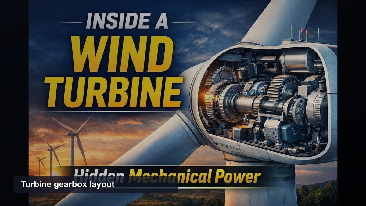
The two applications need different ratios. Wind rotors typically spin at only 10 to 20 RPM, so wind turbine gearboxes commonly use step-up ratios between 40:1 and 135:1. Hydro turbines usually spin faster than wind rotors, which is part of why a hydroelectric gearbox typically needs a smaller ratio to close the gap.
Load pattern is another difference. Wind loads change constantly with gusts and turbulence, which stresses a wind turbine gearbox unevenly. Water flow through a hydro turbine stays comparatively steady, so a hydroelectric gearbox experiences a more consistent load over time. This difference shows up in reliability data. Wind turbine gearboxes are designed for a 20-year service life but commonly fail within 5 to 9 years, largely due to bearing damage from that uneven loading. Hydroelectric gearboxes are not documented with the same shortfall, and steadier loading is a likely reason why.
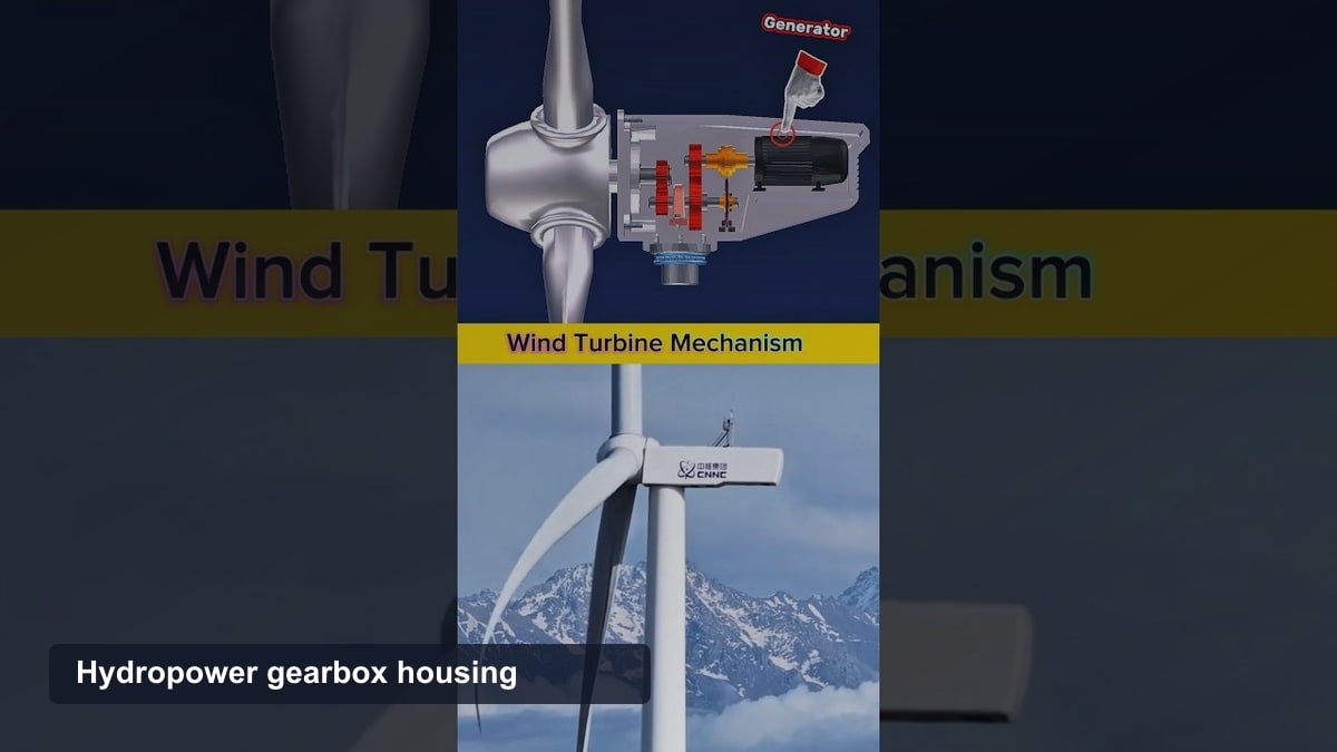
Wind turbine gearboxes also sit inside an elevated nacelle, which makes inspection and repair harder and more expensive than servicing a hydro gearbox at ground level inside a powerhouse.
For technical background, see U.S. Department of Energy hydropower guide.
Hydroelectric Gearbox FAQs
Do All Hydroelectric Plants Use a Gearbox?
No. Plants using multipole synchronous or permanent magnet generators connect the turbine directly to the generator and skip the gearbox entirely.
What Is Another Name for a Hydroelectric Gearbox?
A hydroelectric gearbox is also called a speed increaser or a step-up gearbox, since its main job is raising turbine speed to generator speed.
What Determines a Hydroelectric Gearbox’s Gear Ratio?
The gap between the turbine’s natural rotational speed and the generator’s required speed determines the gear ratio. A low-speed turbine in a low-head plant typically needs a larger ratio than a high-speed turbine in a high-head plant.
How Long Does a Hydroelectric Gearbox Last?
A well-maintained hydroelectric gearbox typically lasts 10 to 20 years, similar to other heavy industrial gearboxes, depending on load, lubrication quality, and maintenance schedule.

Jimmy O’Riley is a UK-based mobile mechanic and automotive diagnostic specialist operating out of Bedfordshire, England. He founded O’Rileys Autos in 2011 with a focus on bringing professional vehicle repairs directly to customers at their homes and workplaces.
With over a decade of hands-on experience, Jimmy specializes in ABS diagnostics, brake system repairs, diesel emissions faults, and DPF cleaning. He is recognized across the UK and Ireland as one of the leading specialists in vehicle braking and emissions systems, earning the title “The DPF King” from his growing online audience.
Jimmy documents real-world automotive repairs through his YouTube channel, which has accumulated over 97,000 subscribers and nearly 2,000 published repair videos. His content covers ABS fault diagnosis, wheel speed sensor testing, brake module replacement, and roadside repair procedures across a wide range of vehicle makes and models.
He is active on YouTube, Instagram, and Facebook under O’Rileys Autos.