A trailer ABS wiring diagram is a schematic that maps the electrical connections between the ABS electronic control unit (ECU), wheel speed sensors, modulator valves, warning lamp, and power supply. Technicians use it to trace faults, verify correct installation, and confirm system configuration before and after repairs.
What Is a Trailer ABS Wiring Diagram?
Federal brake-system rules are published in FMCSA brake systems guidance.
A trailer ABS wiring diagram is a component-level electrical schematic showing every wire, connector, and circuit path in the trailer's anti-lock braking system. It identifies wire gauges, color codes, pin assignments, and resistance values for each circuit.
Trailer ABS wiring diagrams are specific to 3 variables:
WABCO Trailer ABS Blink Code 6: Meaning, Causes, and 3 Reset Methods
ABS and Traction Control Light On: 7 Causes and How to Fix It
- The ABS manufacturer. Examples include WABCO, Haldex, Bendix, and Knorr-Bremse.
- The sensor and modulator configuration (2S/1M, 4S/2M, or 4S/4M)
- The trailer axle type and brake system layout
Using a diagram from the wrong manufacturer or configuration produces incorrect diagnostic results.
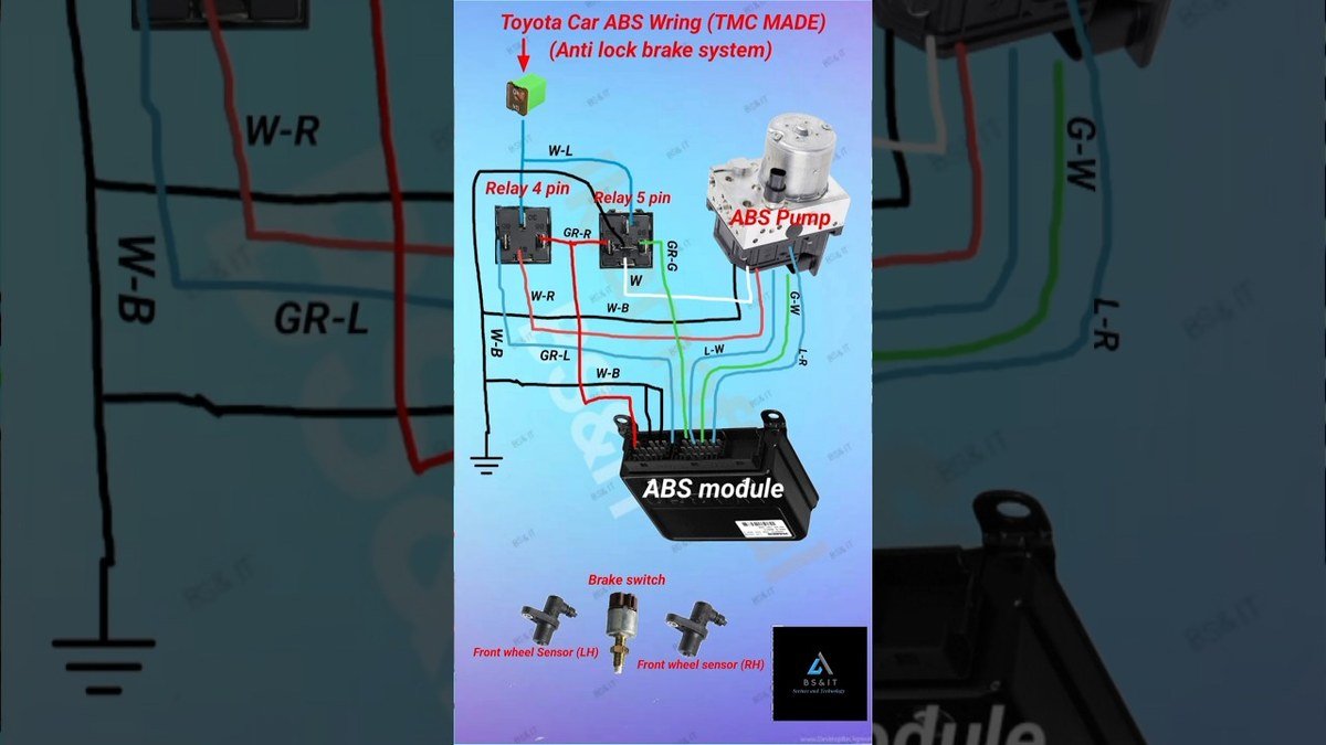
What Are the Main Components in a Trailer ABS Wiring Diagram?
There are 7 main components shown in a trailer ABS wiring diagram:
- ABS ECU (the central processing unit for all brake control signals)
- Wheel speed sensors (passive or active magnetic sensors mounted at each hub)
- Tone rings (toothed rings mounted on the wheel hub that generate speed signals)
- Modulator valves (solenoid valves that control air pressure to each brake chamber)
- ABS warning lamp (mounted on the trailer or visible to the driver via the dashboard)
- Diagnostic connector (a port that allows scan tools to communicate with the ECU)
- Power supply fuse (protects the ECU from current spikes, typically rated at 20A to 30A)
Each component appears in the diagram as a labeled symbol connected by lines that represent wires. The wire lines include color codes and gauge ratings printed alongside them.
How Are Wheel Speed Sensors Wired in a Trailer ABS System?
Each wheel speed sensor connects to the ABS ECU using a 2-wire circuit. One wire carries the sensor signal and the other provides the sensor ground return. The 2 wires are twisted together throughout their length to reduce electromagnetic interference from the trailer's electrical system.
Sensor wiring resistance measured at the ECU connector must fall between 900 ohms and 2,000 ohms on passive variable reluctance (VR) sensors. Readings above or below this range indicate a wiring fault or a failed sensor.
How Are ABS Modulator Valves Wired to the ECU?
Each modulator valve connects to the ABS ECU through a 2-wire solenoid circuit. The ECU supplies battery voltage to the valve and controls braking intervention by switching the ground circuit on and off at high frequency during an ABS event.
Modulator valve coil resistance typically measures between 4 ohms and 7 ohms. A reading outside this range indicates a short circuit, open circuit, or failed valve coil.
What Are the Standard Trailer ABS Wiring Configurations?
There are 4 standard trailer ABS wiring configurations. The number before the "S" indicates sensors and the number before the "M" indicates modulators.
| Configuration | Sensors | Modulators | Typical Application |
|---|---|---|---|
| 2S/1M | 2 | 1 | Single axle trailers |
| 4S/2M | 4 | 2 | Standard tandem axle trailers |
| 4S/4M | 4 | 4 | Full ABS tandem axle trailers |
| 6S/3M | 6 | 3 | Triaxle trailers |
The 4S/2M configuration is the most common on North American tandem axle dry van and refrigerated trailers. Each modulator controls 1 axle and the ECU selects which wheel's sensor signal governs that axle during ABS activation using the select-low principle.
How Is the 7-Pin Trailer Connector Wired for ABS Power?
The ABS ECU receives its 12V power supply through Pin 7 (blue wire) of the SAE J560 7-pin trailer connector. This pin is designated as the auxiliary circuit and is energized whenever the tractor ignition is in the ON position.
The 7 pin assignments for the SAE J560 connector are as follows:
| Pin | Wire Color | Circuit |
|---|---|---|
| 1 | White | Ground (chassis) |
| 2 | Black | Clearance and marker lamps |
| 3 | Yellow | Left turn and stop signal |
| 4 | Green | Right turn and stop signal |
| 5 | Red | Stop lamps |
| 6 | Brown | Tail and running lamps |
| 7 | Blue | Auxiliary (ABS power supply) |
European trailers use a dedicated ISO 7638 7-pin connector specifically for ABS and EBS power. This connector provides a direct battery voltage supply and a separate CAN bus connection for advanced brake system communication between tractor and trailer.
What Do Wire Colors Mean on a Trailer ABS Wiring Diagram?
Wire colors in a trailer ABS wiring diagram identify the function of each circuit. Color coding is standardized across WABCO, Haldex, and Bendix diagrams with minor variations by manufacturer.
| Wire Color | Circuit Function |
|---|---|
| Red | Power supply positive (+12V or +24V) |
| White or Black | Ground return |
| Yellow | Wheel speed sensor signal |
| Green | Modulator valve control |
| Brown | Warning lamp circuit |
| Blue | Diagnostic communication line |
| Orange | Lateral acceleration sensor (where fitted) |
Always verify color coding against the specific manufacturer's diagram before testing. Aftermarket repairs and trailer rewiring jobs sometimes deviate from standard color conventions.
How to Use a Trailer ABS Wiring Diagram to Diagnose Faults
There are 4 primary diagnostic uses for a trailer ABS wiring diagram:
- Identifying which ECU pin corresponds to a specific sensor or valve
- Measuring correct resistance values for each circuit
- Tracing an open circuit or short circuit to its location in the harness
- Verifying correct pin assignment after connector replacement or harness repair
Begin every diagnostic session by pulling the blink code or DTC from the ECU. Use the wiring diagram to locate the specific circuit referenced by that code, then test the circuit with a digital multimeter.
How to Check Wheel Speed Sensor Wiring with a Multimeter
Wheel speed sensor wiring is checked by measuring resistance and AC voltage output at the ECU connector. Disconnect the ECU harness connector before measuring resistance to prevent damage to the ECU.
Follow these 5 steps:
- Set the multimeter to resistance (ohms) mode
- Back-probe the 2 sensor wires at the ECU connector
- Confirm resistance reads between 900 ohms and 2,000 ohms
- Set the multimeter to AC voltage mode and reconnect the ECU
- Rotate the wheel by hand and confirm AC voltage between 0.2V and 2.5V at low rotation speed
A resistance reading of 0 ohms indicates a short circuit between the 2 sensor wires. An open line (OL) reading indicates a broken wire or disconnected sensor.
Where to Find an Accurate Trailer ABS Wiring Diagram
Accurate trailer ABS wiring diagrams are available directly from the ABS system manufacturer. Using a generic or incorrect diagram during diagnosis leads to misidentified faults and unnecessary component replacement.
Reliable sources include:
- ZF Services website (formerly WABCO): zf.com/services
- Knorr-Bremse (Haldex): knorr-bremse.com
- Bendix Commercial Vehicle Systems: bendix.com
- Mitchell1 Pro-Demand and Alldata Repair (subscription-based, covers multiple manufacturers)
- Original trailer manufacturer service portals. Examples include Utility Trailer, Wabash National, Great Dane, and Fontaine Trailer.
Always confirm the diagram matches the ECU part number stamped on the ABS module housing before starting any wiring test. WABCO, Haldex, and Bendix each produce multiple ECU versions with different connector layouts, and pin assignments vary between versions.
Jimmy O’Riley is a UK-based mobile mechanic and automotive diagnostic specialist operating out of Bedfordshire, England. He founded O’Rileys Autos in 2011 with a focus on bringing professional vehicle repairs directly to customers at their homes and workplaces.
With over a decade of hands-on experience, Jimmy specializes in ABS diagnostics, brake system repairs, diesel emissions faults, and DPF cleaning. He is recognized across the UK and Ireland as one of the leading specialists in vehicle braking and emissions systems, earning the title “The DPF King” from his growing online audience.
Jimmy documents real-world automotive repairs through his YouTube channel, which has accumulated over 97,000 subscribers and nearly 2,000 published repair videos. His content covers ABS fault diagnosis, wheel speed sensor testing, brake module replacement, and roadside repair procedures across a wide range of vehicle makes and models.
He is active on YouTube, Instagram, and Facebook under O’Rileys Autos.